Stray Flux Measurement
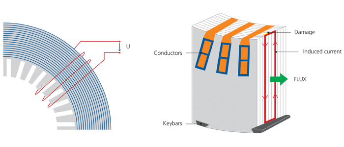
To detect weak spots in the insulation of stator core segments, among other methods a stray flux measurement is used. In this case, a small percentage of the rated flux in the range of 2-10% is induced into the core via an auxiliary winding (Figure 1 left side) [1]. If a short between the lamination occurs, a higher eddy current – driven by the induced voltage from the auxiliary windings flux – causes a higher stray flux as shown in Figure 1 on the right side.
This is detected as a higher stray flux by a Chattock or Rogowski coil scanning the stator surface as explained in Figure 2. [3] The readings of the coil are in mA correlated to a certain position within the stator core. As the measurement coil width and the number of turns of the sensor remains the same for each measurement, a calibration can be obtained prior to each measurement.
When measuring at an injection at 4% of rated flux [1], the excitation of the source does not need to deliver typically more than 2-3 kVA [2]. Even lower power is needed in most machines. This represents the major advantage compared with other methods, such as the full flux measurement, as the power supply and the setup for this test are fast and easy.
A common value at which locations should be investigated is 100 mA of the quadrature current, when measurements are performed at 4% of rated flux and rated frequency [1, 2].