Some things evolve more slowly than others in this fast paced modern world in which we live. Switchgear has historically been built in much the same way that it has been for many decades. The time has come for a new era of switchgear construction; due to advances in technology we can build switchgear to be smaller, lighter and more reliable than ever before. This is the era of Digital Switchgear.
Protection and measurement systems in switchgear have always relied on analog current and voltage signals from traditional instrument transformers (current transformers and potential transformers).
Traditional instrument transformers use a ferromagnetic circuit with secondary outputs that are proportional to the primary current and voltage being measured – 1 A or 5 A for current transformers and 110 VAC for voltage transformers.
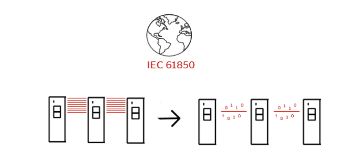
The Digitalisation of Analog Signals
Digital switchgear, on the other hand, uses low power output signals from current and voltage sensors which are inherently safer for personnel. These sensors are often referred to as non-conventional instrument transformers (NCITs) or low power passive current or voltage transformers as per IEC 61869.
These voltage and current sensors which use a different measuring approach can transmit signals greater distances without losing high accuracy levels. These signals can be generated and transmitted without the high heating losses of traditional measurement devices. The secondary outputs for these type of sensors are in the millivolt (mV) range.
With the availability of these new current and voltage sensors, it is possible to build switchgear in a better way: using fewer materials, while being more reliable, more energy efficient and safer for operators than ever before. The time for change is now.
Control Systems
The control systems in switchgear have traditionally been based on using electromechanical devices, these electromechanical protective relays many times had high power requirements (burdens) that needed very large high accuracy current transformers in order to function properly. Today’s modern microprocessor based relays have multifunction, communication, and data logging capabilities (to name a few) all with very low energy burdens requiring only a small amount of energy. This opens up brand new possibilities with respect to the current and voltage measurement devices that can be used. Microprocessor based relays that are compatible with sensors have Low Energy Analog (LEA) inputs. Most sensors can meet these new requirements in a much smaller and less costly footprint. The main criticism of the low power sensors is that they are unable to drive multiple devices. This disadvantage can be eliminated by using Sampled Values data sharing following the IEC 61850-9-2 standard.
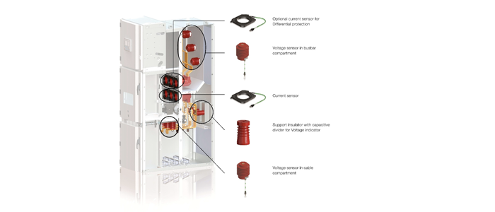
Current and Voltage Sensor
The current sensors are based on Rogowski coils for current measurement and voltage sensors on resistive or capacitive voltage dividers for voltage measurement.
A Rogowski coil is a device used to measure alternating current. It comprises a toroidal winding where the current carrying conductor passes through the center of the toroid. The core, therefore, is pure air versus the ferromagnetic core used in traditional current transformers. The current measured by the sensor is output as a low level voltage signal which is proportional to the derivative of the current. The Rogowski coil has superb performance and operates linearly over a wide dynamic range, from metering to protection, and completely eliminates the main issues of traditional current transformers from the inductive open circuit as well as saturation performance during fault conditions.