- +61 7 3374 2877
- Email Us
Due to industry importance, this series is being re-run with updated information to include industry changes.
Part 1 of this series of articles introduced the requirements of the Australian Work Health and Safety Act and Regulations to identify reasonably foreseeable electrical hazards including arcing hazards. It continued to show how the Australian WHS Regulations requires management of these risks so far as is reasonably practical using a hierarchy of hazard control measures.
It then explained that whilst arcing faults normally last less than a second, they develop over time from an insulation breakdown to single-phase, three-phase and two-phase-and-earth faults with amplitudes much higher than load currents that move away from the source of supply.
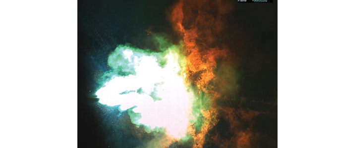
Parts 2 and 3 of this series described how an arcing fault consists of up to three live electrodes with plasma jets ejected from near where the arc columns attach to the electrodes. The plasma arc jets are then inter-connected by filamentary constricted arc columns. All the constricted filamentary columns lie inside a conducting region carrying diffuse currents that are made up of Copper (Cu), Oxygen (O) and Nitrogen (N) atoms and ions. The nearly invisible extremity of the conducting region is referred to as the molecular boundary where the radiation density falls to a level where molecules can survive and conductivity collapses. This leaves the green decaying plasma cloud in the photograph impacting on the victim that causes most of the severe burns during arcing incidents.

Then Part 4 described what happens when human beings with certain personal protective equipment initiate an arcing fault with an electrocution.
The following part 5 provides an engineering introduction on how the Law interacts with performing normal un-energised work. It is NOT legal advice.
What the Law prescribes
Electrical safety in Australia is mandated by the law using Acts of Parliament, Regulations and codes. Safe Work Australia (SWA), which is a tripartite body of government, unions and employers, had a “Model Work Health and safety (WHS) Act” passed in the South Australian parliament in 2011. Also in 2011 Model Work Health and Safety Regulations were passed that include the detail of workplace safety.
The Australian Legislation and its Regulations are legally binding in the Australian states that have endorsed the Model Act and Model Regulations and it is intended that all states will move in this direction. The Australian Industry Group published in December 2011 that the Commonwealth, Queensland, New South Wales, Northern territory and ACT had passed their WHS Acts with an effective date of 1 January 2012. Tasmania has passed its WHS with an implementation date of 1 January 2013.