Low voltage (LV) power cable circuits (<600V) are the backbone of the electrical distribution systems in almost all parts of the world, with the noted exception of North America. There this function is typically provided by medium voltage (MV) power cable circuits (5-35kV). Worldwide there are many more LV cables in operation compared to the number of MV cables.
This also explains why there are many more failures in LV cables when compared to MV cables. Aside from a higher statistical probability for failures in LV cables because of their much larger number, there are other contributing factors:
multitude of cable construction types
multitude of splice designs
variety of assembly & work procedures
Unlike fault locating MV cables, where the vast majority of faults are pinhole or flashover faults that can be found by applying a few main methods and techniques, LV cable fault locating require a larger variety of methods and techniques for the reasons described above. Traditionally experienced customers use a number of different pieces of equipment due to the lack of integrated LV fault locating systems, unlike those which have become state of the art for MV cables.
Megger’s Positioning
Megger Germany has provided equipment for LV cable fault locating for many years, offering a limited product portfolio when compared to its extensive MV cable fault locating product range. Megger VF started to offer a 4kV EZ-Thump unit about 10 years ago, which is complemented by an 3kV Dual Capacitor EZ-Thump, originally designed for the federally owned French Utility Company ENEDIS (formerly EDF). Both units represent a TDR based fully integrated system concept, which offers the necessary technologies and methods to successfully perform LV fault locating on all types of LV cables and circuits, except highly branched circuits. It is estimated that 80% of circuits worldwide represent point to point circuits or circuits with very short T-branches, typically 5-10m. Because both LV circuit scenarios represent about 80% circuits worldwide, many customers prefer a TDR based technology.
Fault locating on LV cables is by no means the same as MV fault locating at a lower voltage as believed many times. LV cables are practically all multi-conductor cables. It is important to understand differences in the actual arrangement of conductor and neutral conductors, cable design, insulation materials and possibly shielding and armour arrangements. All these parameters, together with the fault resistance influence which fault locating method will be the best to successfully locate the fault.
This paper describes a step-by-step protocol to successfully locate faults in LV multiconductor cables. It highlights all potentially necessary steps to locate LV cable faults depending on their nature. Megger’s fully integrated EZ-THUMP 3 and 4 kV LV fault locating systems can provide the required technology in one compact SW controlled and operated, very user-friendly light weight package.
Actual Fault Situation
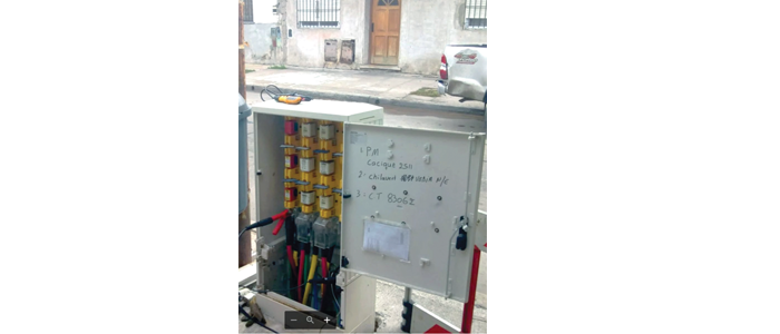
The actual situation involved a 4 conductor (3 phase conductors, 1 neutral) residential LV cable with armour.
Typical residential 3 phase fuse cabinet
The section of (trunk) cable between 2 fuse (switch) cabinets was approx. 100m long and serviced 3 homes, each via a T splice (joint), being approx. 30m apart.
Fault Locating Protocol
In order to proceed, the fuses at each individual house service within that section of cable needed to be removed. It is important to maintain the proper clearance between the contact points in the fuse box or termination box in order to safely apply a higher voltage than operating voltage as may be required in the particular situation for locating the fault.
1. Check the insulation resistance between all unique combinations of conductors incl. the armour by applying 500VDC and get IR readings (unpopulated fields).
Typically, the armour is bonded to the system ground (earth). In equipment that offers a F-OHM safety feature, the IR measurement is in “high voltage” mode and requires a bond between HV Return and system ground (earth) to close the safety loop. Therefore, all measurements are taken between the selected “hot” conductor & HV Return, which is de facto grounded. In this case it was somewhat surprising that all IR values were on the low side, between 50kΩ & 2kΩ. Theoretically one could have cable faults in several different locations of all 4 conductors; in this case all “faults” appear to be in the same location, e.g. like in a splice. This was a first indication that the cable fault was potentially in one of the T splices.