The IEEE committee revising Std 81, amongst others, have wrestled with this question, and currently, there is no consensus. To answer the question “Are we really testing R, Z or something else?” the authors have investigated and tested a range of scenarios and instruments and sought to be definitive. This article presents their methods, results, and conclusions.
Why are we asking this question and what are we testing?
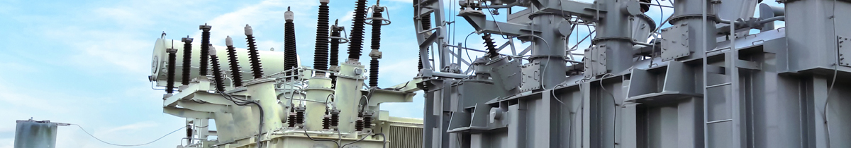
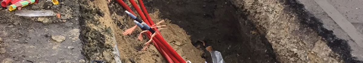
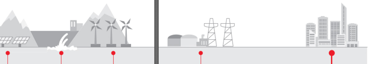
For an earthing system to be effective, its performance needs to be adequate for the power system attached to it and all the factors that affect its performance need to be considered. The performance of the earthing system is entirely dependent of the ground in which it is placed. The soil composition, existing infrastructure and mineral/moisture content all affect the apparent resistivity of the soil and thereby the performance of the earthing system. To assess the performance of an earthing system requires tests
of parameters associated with or affecting that performance, including soil resistivity, EPR, resistance of earth grid, loop impedance, and continuity.
How are we testing?
To measure each of the aforementioned parameters current must be injected into the earthing system and/or the surrounding soil and the response measured. The injected current can be either a ‘Switched DC’ or an ‘AC current’ injection.
In both methods, the current is known, and voltage is measured. The question we are investigating here is “for a switched DC injection how should the measured voltage be interpreted”?