APTP Articles

Can Common PD Emissions be Detected at Multiple Frequencies?

Partial Discharge surveys are a trusted and successful part of the modern Asset Management plan as a means of condition assessment for multiple items of High Voltage Substation equipment including, for example Circuit Breakers, Cables, Instrument Transformers and Terminations.

These mature and widely accepted services have proven effective at providing valuable actionable data in the form of targeted maintenance interventions, Asset lifecycle management and Network planning functions to the Electrical Distribution Industry and for HVDS in New Zealand at least, TEV and Ultrasonic methods have been synonymous with reliable condition data for some 20 years.

TEV measurement, in the band 3 – 80MHz for internal void type discharges and Ultrasonic detection, tuned to 40kHz for surface type activity would be expected to be reasonably well understood by industry but have you ever wondered whether there are other techniques available for these common signals, and why should we bother anyway?

UHF detection in the range 47 – 1000MHz was developed for working at greater distances, or when non-contact must be maintained such as in High Voltage Open Terminal switchyards and a frequency of 800MHz is ideal for Electrical ‘arcing’ at the same time rejecting Corona signals, while we have personally found that 806 – 808MHz works well to tune out interference from nearby Cell towers. 

Here we examine examples of both TEV and Ultrasonic Discharge that were also identified by UHF and compare waveforms from the stand-alone PD Hawk Instrument used on these surveys, along with a wildcard third option for your further consideration.

Case Study 1

Case Study 1
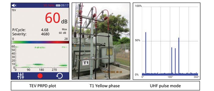
Firstly, elevated TEV signals were present on various indoor 11kV switchboard panels and Incomer cables (max 31dBmV) while outside the UHF sweep led us to Transformer T1, whereby a subsequent TEV measurement on the Yellow phase 33kV cable confirmed 60dBmV at a pulse rate of 4.68ppc. The Phase resolved Partial Discharge plot (PRPD) is not typical of an internal void type pattern however does exhibit the phase resolved signal indicative of discharge. Turning our attention to the UHF pulse mode scan we see two groupings spaced 180 degrees apart and note the 4 pulses per cycle (one screen width) consistent with the TEV screen (UHF scan completed at 807MHz at gain of 27). Note Ultrasonic was also present from the top clamps on the insulated risers and the floating non-referenced nature of this arrangement is likely responsible.

Case Study 2
Secondly, at a different location on the same Network high Ultrasonic was present from the base of the Red phase Bushing on a tired looking Local Service Transformer and you can make out the white residue at the discharge site ‘clouding’ the porcelain surface. The PRPD is near textbook in shape, again displaying 180 degree separation inferring discharge in each half cycle while surface PD ‘discharges’ at a much higher rate per cycle (can be upwards of 30ppc) and although not directly measured is graphically represented in the UHF result. This defect may not be at risk of imminent failure but continued Oil leaks together with the dirty surface / contaminants could conspire to flash over under ideal conditions for what ought be a relatively easy clean-up.

By Greg Linton, HV Diagnostic Services Limited