APTP Articles

Electricity Distribution Using Two Wire Single Phase

There are multiple ways to design the electricity network for distributing power at 11 to 38 kV. From a standards point of view, networks are either designed to the IEEE North American standard, relying on a four-wire system with phase-to-ground transformer connections, or to the European style IEC network relying mostly on larger 3 phase transformers.

Under the European style of electricity distribution, there are three methods of network design. In descending order of power transfer capability, these are:

  • Three Wire Three Phase
  • Two Wire Single Phase
  • Single Wire Earth Return

The vast majority of European power distribution uses the three wire three phase method. The remaining two methods of electricity distribution are generally applied to lightly loaded rural feeders, where the load does not justify the cost of running the three-phase network out to remote locations.

Single wire earth return distribution uses only one line, where the circuit return path is through an earth connection at the far end of the line. This is the cheapest method of power distribution but has issues for safety. Failing earths break the circuit, and worse yet, failing earths at the far end of the line can introduce dangerous step potentials. 

The safer alternative is to rely on two wire single phase, where the return path of current does not rely on the earth connection in proximity to the public. 

In this article, we review the application of two wire single phase distribution, and how to protect and control these feeders with auto-reclosing circuit breakers.

Figure 1 Basic Connection Diagram for Phase to Phase connection

Two Wire Single Phase Distribution

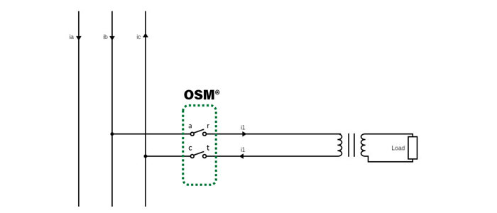
Two wire distribution lines are connected to the three phase European style backbone feeder. They are usually connected phase to phase, as shown in Figure 1.

Phase to Phase Connected Single Phase Spur

In this connection topology, it is equivalent to taking a three-phase spur, but omitting one of the lines. 

The voltage between the two lines in the single-phase arrangement is the phase-to-phase voltage of the backbone. That is, if the feeder backbone is 22 kV phase to phase, then the two-wire single phase voltage is also 22 kV phase to phase, with voltages 120 degrees apart. 

The current however is 180 degrees apart. This introduces the limitation of single-phase distribution from a three-phase backbone – current unbalance seen on the main line.

The load at the end of the line is connected through a phase-to-phase transformer. 

Protecting Two Wire Single Phase – Connecting an OSM Recloser

In Figure 1, the two circuit breaker icons are representative of a NOJA Power OSM Recloser two phase device.

Each phase has a current transformer, and voltage sensors on either side of the interrupter.

NOJA Power OSM Recloser terminals are designated ABC and RST. In the two-pole connection topology, only phases AR and CT are connected, with the B to S phase either missing (when using a two-pole device), or left disconnected when using a three phase device. 

Using a three-phase device is common practice when future network augmentation would suggest conversion to three phase
is likely. 

About the Author

NOJA Power