APTP Articles

The Evolution of Distribution Earthing Design

The last two decades has been an interesting journey for the distribution earthing designer. Not so long ago all the earthing designer was required to achieve was a simple target local earthing resistance. Popular values were 1 Ohm or 10 Ohms, or possibly 15 or 30 Ohms, depending on what was being earthed, however that changed for several reasons.

Electric shocks incidents involving people in their homes due to faults on HV distribution assets in the neighbourhood reminded engineers of the risk to the public from these assets. Concerns about these risks, whilst valid, were tempered by the realisation that electricity is an established utility. The public, including you and me, all take for granted the ongoing supply of electrical energy. So, some Australian earthing engineers teamed up to understand how to do earthing design better. Now the world is listening to Australia on this subject.

What constitutes a ‘safe’ design?

The designer of distribution earthing systems has a problem. How to determine a ‘safe’ and affordable design within a quite limited design budget? And this begs the question what constitutes a ‘safe’ design? 

The last two decades have seen a lot of work done to answer the question “What constitutes a ‘safe’ earthing system”. As those close to this area know, it’s more a question of reducing risks to acceptably low levels in accord with current best practices and to as low as reasonably practicable. Rather than designs being assessed with a binary outcome, i.e., either ‘satisfactory’ or ‘unsatisfactory’, best practice suggests that ‘safe’ is no longer the right approach. The ENA Power System Earthing Guide (EG-0) Part 1 Management Principles documented how earthing risks could be quantified and an approach for completing designs using quantitative risk assessment. Recently revised Australian Standards such as AS2067, AS4853 and AS7000 now also follow this approach. Earthing designs are now approached through the lens of reducing risk levels through the transition from unacceptable to negligible risk.

Electrical conduction in the heart

And so, the world has changed for earthing designers! They now need to understand the variables relevant to quantifying the risk associated with people in shock situations. Key questions these standards raise, and address are: 

  • What magnitude of current through the heart will be lethal?
  • What other variables affect the answer to the first question?
  • If we want to quantify the risk, how do we do that?

These questions lead the earthing designer to recognise that there are a lot of variables to be considered to assess the risks associated with earthing system design properly. 

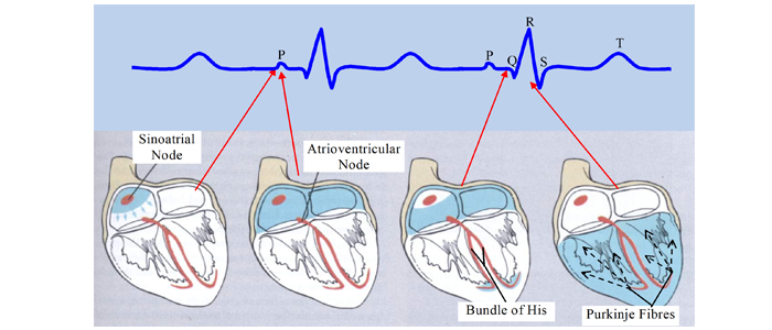
It’s not enough to understand current flow in conductors and the earth, they must understand the impact of electric current on people. The human heart is not only sensitive to the magnitude of current through it, but also to the duration of that current. If the normal functioning of heart muscle cells is interrupted by sufficient current at the wrong part of the heart cycle, then the probability of ventricular fibrillation increases dramatically. This understanding helps the designer appreciate the value of fast fault clearing times, which is reflected in the applicable safety criteria. So, a local fuse that will clear a fault in less than 0.2s may mean a simple cost-effective local earthing system will comply with the requirements of relevant Australian standard touch voltage criteria. If, however it takes upstream protection over 1s to clear an earth fault, designing a compliant earthing system may be a very difficult task indeed.

About the Author

By Gordon McMurray – Specialist Engineer, Safearth